Product Description:
The SKLUW sanitary vortex flowmeter is mainly used for flow measurement of industrial pipeline medium fluids. Its characteristics are small pressure loss, large range, high accuracy, and it is widely used in industries such as food and chemical for the measurement and control of compressed air and general gases (oxygen, nitrogen, hydrogen, natural gas, coal gas, etc.), water, and liquids
1、 Working principle of sanitary vortex flowmeter
If a non streamlined vortex generator (fluid barrier) is set up in the fluid, two regular vortices are alternately generated from both sides of the vortex generator. This type of vortex is called a Karman vortex street, as shown in the following figure.
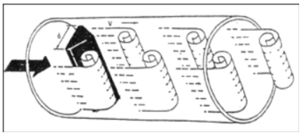
The vortices are arranged asymmetrically downstream of the vortex generator. Assuming the frequency of vortex occurrence is f, the average velocity of the incoming flow of the measured medium is V, the width of the upstream face of the vortex generator is d, and the diameter of the body is D, according to the principle of Karman vortex street, the following relationship is obtained:
F=StV/d (1)
In the formula:
F - frequency of Karman vortex generated on one side of the body
St Strouhal number (dimensionless number)
V - Average flow velocity of fluid
D - width of vortex generator
From this, it can be seen that the instantaneous flow rate can be calculated by measuring the separation frequency of the Karman vortex street. Among them, Strouhal number (St) is an dimensionless unknown variable, and the following figure shows the relationship between Strouhal number (St) and Reynolds number (Re).
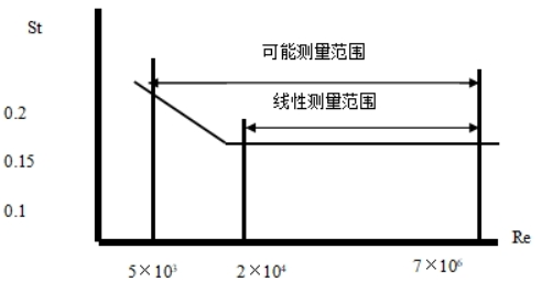
In the straight part of the curve table with St=0.17, the frequency of vortex release is proportional to the flow velocity, which is the measurement range of the vortex flow sensor. As long as the frequency f is detected, the flow velocity of the fluid inside the pipe can be obtained, and the volumetric flow rate can be calculated from the flow velocity V. The ratio of the measured number of pulses to the volume is called the instrument constant (K), as shown in equation (2)
K=N/Q (1/m ³) (2)
In the formula: K=instrument constant (1/m ³).
N=number of pulses
Q=Volume flow rate (m ³)
2、 Main technical specifications of sanitary vortex flowmeter
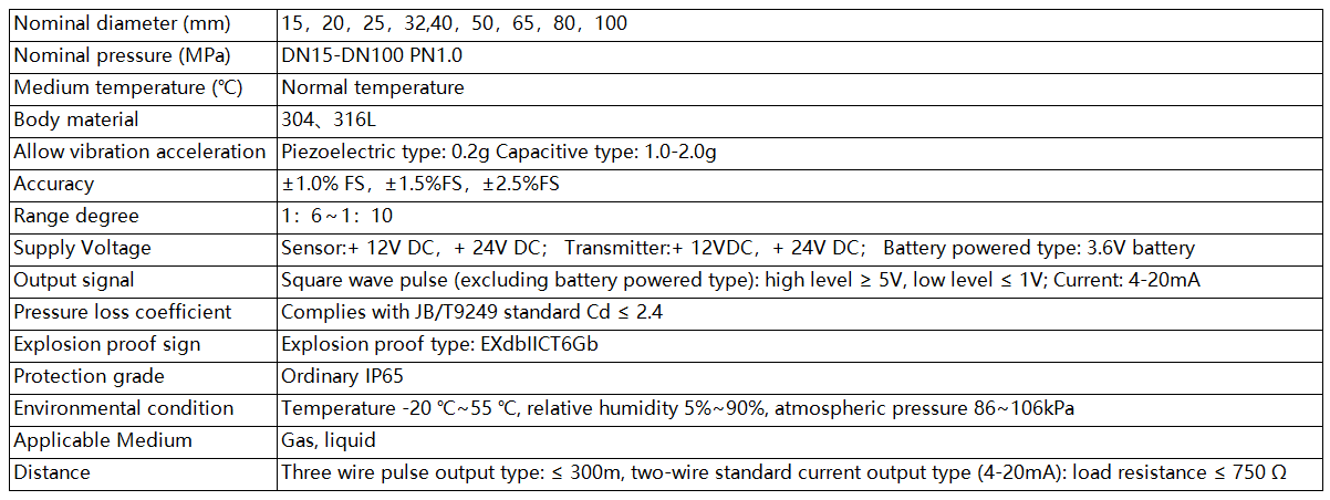
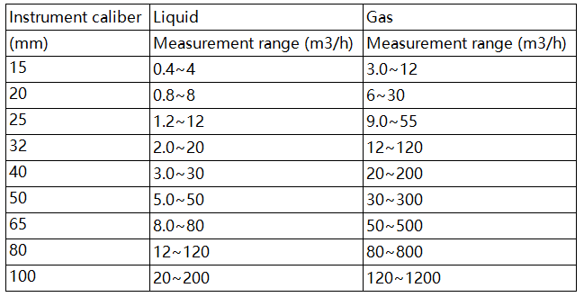
Flow range table of sanitary vortex flowmeter under reference conditions:
Sanitary vortex flowmeter body external dimensions:
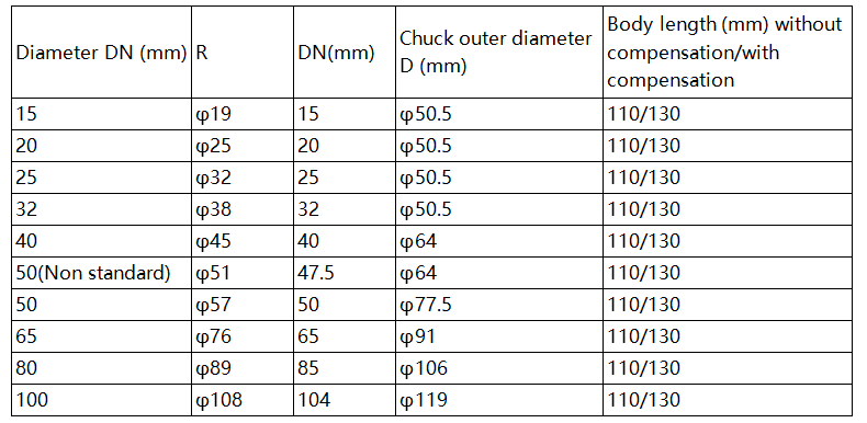
Selection of sanitary vortex flowmeter products:
| Model | Caliber | Code and Function |
| SKLUW | DN15~DN100 |
|
|
| Code | Function 1 |
| N | No temperature and pressure compensation |
| Y | Temperature and pressure compensation |
| Code | Output signal |
| F1 | 4-20mA output (two-wire system) |
| F2 | Pulse |
| F3 | RS485communication interface |
| F4 | HARTprotocol |
| Code | Measured media |
| J1 | liquid |
| J2 | Gas |
| Code | Function 2 |
| E1 | Level 1.0 (applicable to liquids) |
| E2 | Level 1.5 |
| E3 | Level 2.5(DN15 DN20) |
| T1 | Normal temperature |
| P1.0 | 1.0MPa |
| D1 | Internal 3.6V power supply (without output) |
| D2 | DC24V power supply |
| B | Stainless steel (body material 304) |
| BF | Stainless steel (body material 316) |
Ordering Instructions
Dear user, when you choose our company's products, please do the following:
1. Carefully verify the operating conditions of the tested medium, including temperature, pressure, pipe diameter, and other process parameters.
2. Carefully check the flow range of the measured medium, especially the minimum flow value, to ultimately determine the diameter and piping parameters of the instrument to be used.
3. Determine the installation location of the instrument, ensure the straight pipe section, and create favorable environmental conditions for the installation and maintenance of the instrument.
4、 Installation requirements for sanitary vortex flowmeter
The correct installation of instruments is an important part of ensuring their normal operation. If not installed properly, it can affect the accuracy of instrument use, and in severe cases, it can affect the service life of instruments and even damage them.
A、 Installation environment requirements:
1. Try to avoid strong electrical equipment, high-frequency equipment, and strong switching power supply equipment as much as possible. The power supply of the instrument should be separated from these devices as much as possible.
2. Avoid direct effects from high-temperature heat sources and radiation sources. If installation is necessary, insulation and ventilation measures must be taken.
3. Avoid high humidity and strong corrosive gas environments. If installation is necessary, ventilation measures must be taken.
4. Vortex flow meters should be avoided from being installed on pipelines with strong vibration as much as possible. If installation is necessary, pipeline fastening devices must be installed at 2D upstream and downstream locations, and anti vibration pads must be added to enhance the anti vibration effect.
5. It is best to install the instrument indoors, and when installing outdoors, attention should be paid to waterproofing. Special attention should be paid to bending the cable into a U-shape at the electrical interface to prevent water from entering the amplifier housing along the cable.
6. There should be ample space around the instrument installation point for wiring installation and regular maintenance.


